From inside (document excerpt):
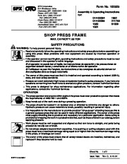
Form No. 102525 Assembly & Operating Instructions for: 014-00094 1852 014-00095 211750 1850 61309 1851 SHOP PRESS FRAME MAX. CAPACITY: 55 TON SAFETY PRECAUTIONS WARNING: To help prevent personal injury, · · Read and carefully follow the operating instructions and safety precautions before assembling or using this press. Most problems with new equipment are caused by incorrect operation or assembly.
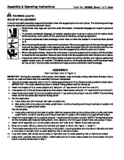
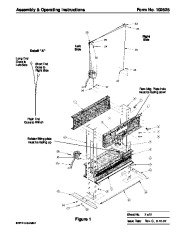
If the operator cannot read English, operating instructions and safety precautions must be read and discussed in the operator’s native language. Si el operador no puede leer el inglés, las instrucciones de operación y las precauciones de seguridad deberán leerse y comentarse en el idioma nativo del operador. Si l’utilisateur ne peut lire l’anglais, les instructions et les consignes de sécurité doivent lui être expliquées dans sa langue maternelle. The owner of this press must see that it is installed and operated according to federal (OSHA), state, and local safety standards. Presses can exert extremely high forces at moderate hydraulic pump pressures. If you have any questions concerning how much force is exerted at a given pressure, contact Technical Services. This press is designed for shop maintenance applications. For information regarding other applications, contact the Technical Services. The press operator and anyone within sight of the press must wear protective eyewear that meets the requirements of ANSI Z87.1 and OSHA. Keep hands out of the work area during a pressing operation. The press should be located in an isolated area or shielded to minimize any danger to others. Hydraulic pressure can cause materials to break, possibly resulting in personal injury. It is impossible for the manufacturer to provide practical “all-purpose ” shielding because this is a general purpose press that can be used in many different applications. The owner of the press must supply shielding that is practical and necessary for a particular application. Some safety is provided by wrapping the work in a protective blanket, such as those offered in our catalog, before applying pressure. Work pieces must be well supported and aligned so that ram force is straight, and parts being pressed do not slip out or break. Do not stress adapters beyond their capacities. Any pushing or pulling adapters used with this press must have a maximum tonnage rating equal to or higher than the maximum tonnage rating of the press, or breakage can occur. The owner of the press must ensure that all safety-related decals are installed, maintained, and replaced if they become hard to read. · OPERATION Sheet No. SPX Corporation 1 of 2 Issue Date: Rev. C, 8-16-02 Assembly & Operating Instructions WARNING (cont’d) BOLSTER ADJUSTMENT Form No. 102525, Sheet 1 of 2, Back A winch and cable assembly support the bolster when the support pins are not in place. The following warnings must be observed to prevent personal injury: · Keep hands, feet, legs, etc. out from under the bolster. Accidental slippage can result in personal injury. · · To prevent accidental slippage, all bolster support pins must be in place and all cables slack before placing a work piece on the press bed or starting a pressing operation. To prevent accidental cable breakage, never raise or lower the bolster if a load has been placed on it. When lowering the bolster, remove the work piece. Place one support pin all the way through each front and the back upright in the highest hole under the bolster that will not interfere with the new bolster position. Remove your hands from the support pins after the pins are in place. When raising the bolster, remove the work piece. Leave the support pins in place until the bolster is raised to its new position. Remove your hands from the support pins after the pins are in place. Inspect the entire length of the lifting cables at least every three months, and replace cables that appear frayed, worn, or crushed. The cables must run on the pulleys easily, and the pulleys must be free to turn. Correct cable maintenance helps prevent accidental cable breakage. ASSEMBLY (Item numbers refer to Figure 1) IMPORTANT: During the assembly of the press, hand tighten nuts and bolts unless otherwise directed. Use a wrench on nuts and bolts after the assembly has been completed. 1. Place lower bolster assembly (Item #10) on 4 ” blocks approximately 30 ” long. Blocks must lay parallel to bolster sides. IMPORTANT: The cable attaching holes in bolster lifting plates must be facing up. 2. Attach foot angles (#13) to press uprights (#4) using two 1/2 ” cap screws (#16) and hex nuts (#7). 3. Insert spacer (#21) through press uprights and foot angles. Attach spacer using two 1/2 ” washers (#20) and nuts (#7). 4. Attach back upper bolster (#1) to top of uprights using six 1 ” cap screws (#6) and jam nuts (#5). NOTE: The mounting holes for the ram plate (#9) must be facing down.


 SPX OTC 014 00094 1852 014 00095 211750 1850 61309 1851 SHOP PRESS FRAME Owners Manual - 1 of 4
 SPX OTC 014 00094 1852 014 00095 211750 1850 61309 1851 SHOP PRESS FRAME Owners Manual - 2 of 4
 SPX OTC 014 00094 1852 014 00095 211750 1850 61309 1851 SHOP PRESS FRAME Owners Manual - 3 of 4
 SPX OTC 014 00094 1852 014 00095 211750 1850 61309 1851 SHOP PRESS FRAME Owners Manual - 4 of 4