From inside (document excerpt):
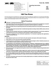
SPX Form No. 102342 Operating Instructions for: 1857 1858 60534 100 Ton Press This heavy duty press can handle all your really tough pressing jobs. Wide open uprights (over 12 “) allow easy side loading.
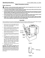
The ram head glides smoothly along the upper bolster on rollers, allowing fast and easy horizontal adjustments. The upper bolster can be lowered eight inches for convenient positioning. Safety Precautions Warning: To help prevent personal injury, · Read and carefully follow the operating instructions and safety precautions before assembling or using this press. Most problems with new equipment are caused by incorrect operation or assembly. Read and carefully follow the operating instructions and safety precautions for the pump and ram used with this press. The owner of this press must see that it is installed and operated according to federal (OSHA), state, and local safety standards. Presses can exert extremely high forces at moderate hydraulic pump pressures. If you have any questions concerning how much force is exerted at a given pressure, contact Technical Services. This press is designed for shop maintenance applications. For information regarding other applications, contact Technical Services. Operation Safety glasses must be worn at all times by the press operator and anyone within sight of the press. Keep hands out of the work area during a pressing operation. Locate the press in an isolated area, or shield the press to minimize danger to others. Hydraulic pressure can cause materials to break, possibly resulting in personal injury. It is impossible for the manufacturer to provide practical “all-purpose ” shielding because this is a general purpose press that can be used in many different applications. The owner of the press must supply shielding that is practical and necessary for each application. Some safety is provided by wrapping the piece in a protective blanket, such as those offered in the OTC catalog, before applying pressure. Work pieces must be well supported and aligned so that ram force is straight, and parts being pressed cannot slip out or break. To prevent accidental slippage, bolster support pins must be in place and all cables slack before placing a work piece on the press bed or starting a pressing operation. Stay out from underneath the bolster. Do not stress adapters beyond their capacities. Any pushing or pulling adapters used with this press must have a maximum tonnage rating equal to or higher than the maximum tonnage rating of the press, or breakage can occur. The owner of the press must ensure that all safety-related decals are installed, maintained, and replaced if they become hard to read. Sheet No. Issue Date: Litho in USA 1 of 2 Rev. 6-15-92 Operating Instructions Bolster Adjustment Form # 102342, Sheet 1 of 2, Back Safety Precautions (cont’d) Warning: A winch and cable assembly support the bolster when the support pins are not in place. The following rules must be observed to prevent personal injury: · To prevent accidental slippage, all bolster support pins must be in place and all cables slack before placing a work piece on the press bed or starting a pressing operation. When lowering the bolster, remove the work piece. Place one support pin all the way through each front and the back upright in the highest hole under the bolster that will not interfere with the new bolster position. Remove your hands from the support pins after the pins are in place. When raising the bolster, remove the work piece. Leave the support pins in place until the bolster is raised to its new position. Remove your hands from the support pins after the pins are in place. Inspect the entire length of the lifting cables at least every three months, and replace cables that appear frayed, worn, or crushed. The cables must run on the pulleys easily, and the pulleys must be free to turn. Correct cable maintenance helps prevent accidental cable breakage. Assembly Remove banding from the press and shipping pallet, and remove all cartons. Stand the press upright. Refer to the parts list and follow these instructions during the assembly of hydraulic components and accessories. 1. Remove the l


 SPX OTC 1857 1858 60534 100 Ton Press Owners Manual - 1 of 3
 SPX OTC 1857 1858 60534 100 Ton Press Owners Manual - 2 of 3
 SPX OTC 1857 1858 60534 100 Ton Press Owners Manual - 3 of 3