From inside (document excerpt):
Form No. 107344 Operating Instructions for: 516160 Heavy Duty Flywheel Adapter for OTC 5018 Max. Capacity: 200 lbs. The OTC Flywheel Adapter is used on the OTC 5018 Clutch Handler for the removal and installation of the 14 ” and 15-1/2 ” flywheel assemblies found on many heavy-duty vehicles. Refer to Form #107299 for instructions about using the clutch handler (OTC #5018). Safety Precautions WARNING: To prevent personal injury and damage to equipment, · Read, understand, and follow all instructions.
Power Tool User Manual Free Download. HAVC Operator’s Manual. Auto AC Lift Power Free Instruction Manual Download PDF.
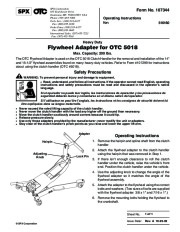
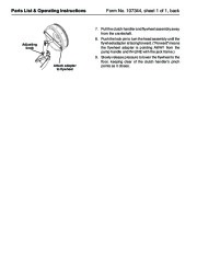
If the operator cannot read English, operating instructions and safety precautions must be read and discussed in the operator’s native language. Si el operador no puede leer inglés, las instrucciones de operación y las precauciones de seguridad deberán leerse y comentarse en el idioma nativo del operador. Si l’utilisateur ne peut lire l’anglais, les instructions et les consignes de sécurité doivent lui être expliquées dans sa langue maternelle. Never exceed the rated lifting capacity of the clutch handler. Never move the clutch handler with the load any higher off the ground than necessary. Move the clutch handler cautiously around corners because it could tip. Release pressure slowly. Use only those adapters provided by the manufacturer; never modify the unit or adapters. Stay clear of the clutch handler’s pinch points as you raise and lower the upper lift arm. Adapter Hairpin Operating Instructions 1. Remove the hairpin and spline shaft from the clutch handler. 2. Attach the flywheel adapter to the clutch handler using the hairpin that was removed in Step 1. 3. If there isn’t enough clearance to roll the clutch handler under the vehicle, raise the vehicle’s front end. Position the clutch handler under the vehicle. 4. Use the adjusting knob to change the angle of the flywheel adapter so it matches the angle of the flywheel assembly. 5. Attach the adapter to the flywheel using the correct bolts and washers. (Two sizes of bolts are supplied with the flywheel adapter: 3/8 x 1 ” and 7/16 x 1 “.) 6. Remove the mounting bolts holding the flywheel to the crankshaft. Adjusting Knob Lock Pin Sheet No. Issue Date: SPX Corporation 1 of 1 Rev. A 10-25-02 Parts List & Operating Instructions Form No. 107344, sheet 1 of 1, back 7. Pull the clutch handler and flywheel assembly away from the crankshaft. Adjusting knob 8. Push the lock pin to turn the head assembly until the flywheel adapter is facing forward. ( “Forward ” means the flywheel adapter is pointing AWAY from the pump handle and IN-LINE with the jack frame.) 9. Slowly release pressure to lower the flywheel to the floor, keeping clear of the clutch handler’s pinch points as it closes. Attach adapter to flywheel …


 SPX OTC 516160 Flywheel Adapter Owners Manual - 1 of 2
 SPX OTC 516160 Flywheel Adapter Owners Manual - 2 of 2